Drag reduction
Hydrodynamic performance
The Salvinia effect is based on the combination of hydrophobic pillars with hydrophilic tips at the surface enables the preservation of an air layer when submerged in water.
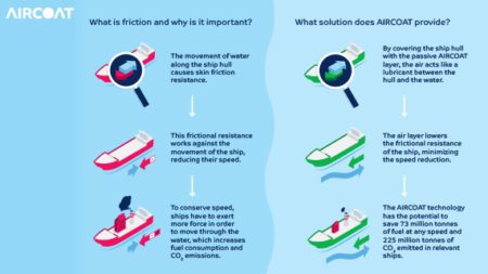
Due to the lower viscosity of air in comparison to water (approx. 50 times at ambient conditions) a reduction in skin friction occurs when overflowed by water.
The design of the surface structure (size and geometry) and its chemical surface properties (contact angle) strongly influence the air retainment capacity and the drag reduction. This is investigated by experiments and numerical simulations.
Experiments
Different experimental approaches are applied to quantify the drag reduction and to investigate the air retainment. The applied methods allow testing of different sample sizes at different Reynolds numbers.
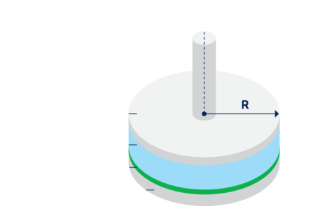
Rheometer measurements
A plate-plate geometry has been used to characterise the effect of different structure geometries and sizes on drag reduction at laminar flow. With increasing structure size a rise in drag reduction appears.
Laser Doppler Anemometry (LDA)
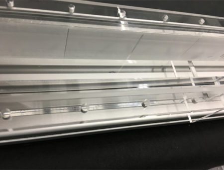
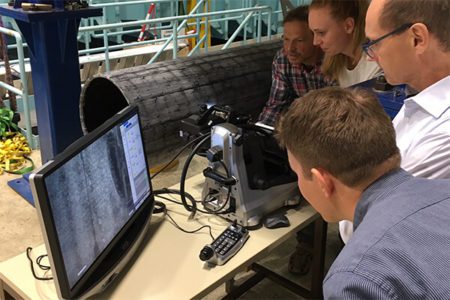
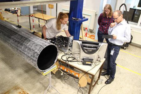
flow channel
The goal here is to determine an actual velocity profile normal to the AIRCOAT surface. The laboratory experiment is being run by Fraunhofer Center for Maritime
Logistics and Services CML.
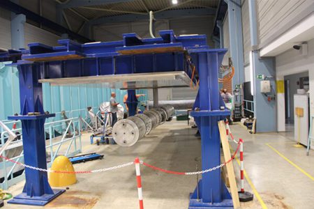
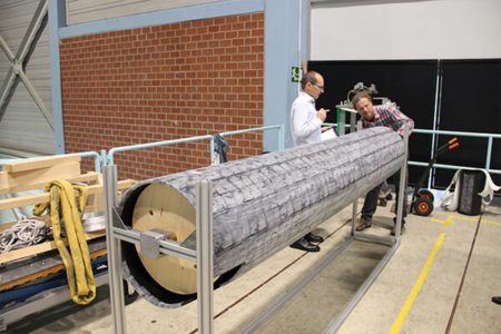
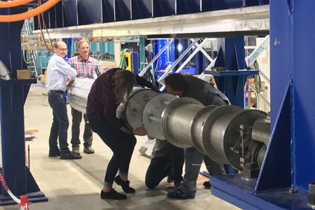
CML designed a three metre long flow channel.
To properly gather the information on the velocity profile CML had to establish a stationary water flow in the measurement section. The tank is designed to reach a maximum flow velocity of 0.5 m/s.
How does it work?
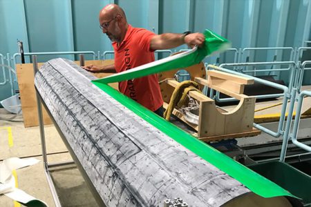
The back of the test section is removed and is coated with AIRCOAT.
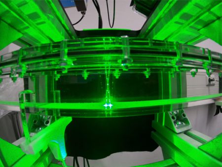
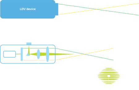
Two lasers are crossed within the test section of the flow channel. A particle crossing the intersection, also called the measurement volume, can be detected by the receiving lens. Based on the Doppler effect the velocity of the crossing particle can be detected and is recorded.
Laser Doppler Velocimeter show high accuracy and a spatial resolution down to a few micro metre.
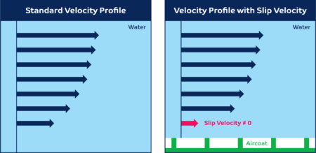
The presence of an air layer increases the velocity of the particles when it is close to the wall. If we observe the particles having a high velocity close to the layer, we know the friction has been reduced.
Cavitation tunnel experiments
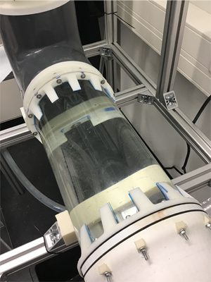
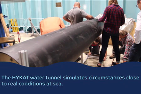
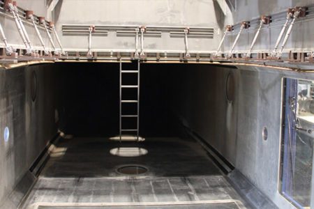
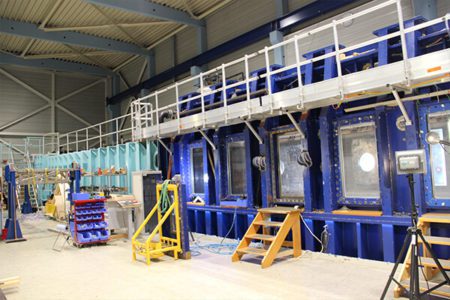
The HYKAT cavitation tunnel of HSVA (Hamburg Ship Model Basin) research centreallowed operational tests to be run on the samples designed by KIT (Karlsruhe Institute of Technology) with visual control and hydrodynamic conditions close to real conditions.
The water speed went up to 10 m/s in order to measure the effect of air degradation by degassed water and regeneration of the air layer in
saturated water.
Optical techniques have been used to visualise the air trapping effect and the fluid flow and investigate the boundary layer.
These experiments allowed us to observe the importance of the protection layer during the application of the AIRCOAT structure and the air retaining properties of the structure of the first prototypes.
In a next step, drag measurements are planned to investigate the drag reduction effect in a near-operational environment.
AIRCOAT first test
in open water
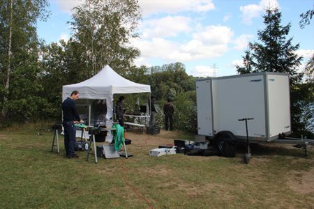
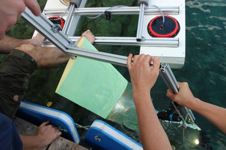
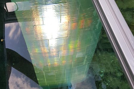
An air layer quantification and monitoring test was lead by CML in 2020. A device was built to a fixed light source with a camera under different defined angles. The results from the tests were used to better observe a foil coated with AIRCOAT in an open water test. The team observed and were able to evaluate the presence of an air layer.
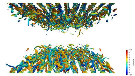
Visualization of turbulent vorticies by the Q criterion
(pillars L+= 80, Reτ = 300)
Numerical simulations
The effect of different structure designs has been investigated in a one-phase fully developed turbulent channel flow. The effect of the air keeping surface has been modelled by different approaches.
Turbulence has been considered by Direct Numerical Simulation (DNS) and Reynolds Averaged Navier Stokes (RANS).
These simulations are lead by BIC – Biomimetics-Innovation-Centre, Bremen University of Applied Sciences
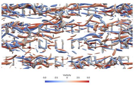
Exposed DNS Calculation of pillars
(size L+= 157, Reτ = 180)
Direct Numerical Simulation
DNS resolves the turbulent flow structure and is used to examine the interaction of the surface structure with the flow in detail. The picture shows a turbulent channel flow over a surface structure consisting of pillars in two sizes. One can see that the bigger structures strongly influence the distribution of the turbulent vortices. The drag reduction increases from spanwise grooves, followed by holes, pillars, and streamwise grooves as well as with growing structure size.
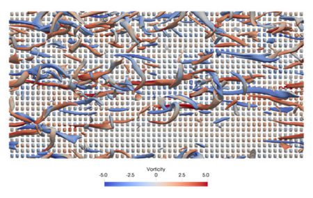
Exposed DNS Calculation of pillars
(size L+= 20, Reτ = 180)
Reynolds Averaged Navier Stokes
RANS simulations: with this method the drag reduction for a complete vessel at high Reynolds numbers (ratio of inertial forces to viscous forces) can be calculated. Based on the findings of the DNS simulations, boundary conditions / wall functions are developed to model the effect of the air layer.

